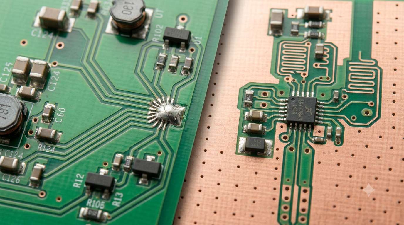
“Should GND be gathered at a single point, or made into a solid plane?”
This is a common question in GND design. Search around and you’ll find articles saying “single-point ground is correct” and others saying “use a ground plane,” leaving you unsure which is right.
The short answer: both are correct — but you need to use them differently depending on frequency. In this article we organize the principle of each and the conditions under which it applies.
- Why the Way You Route GND Matters in the First Place
- Single-Point Ground — The Idea of Making the Common Impedance Zero
- Ground Plane (Solid Ground) — The Idea of Driving the Impedance Right Down
- Comparing in uSimmics — Single-Point Ground vs. Ground Plane
- The Approach Changes with Frequency — In Summary
- Summary
- Related Articles
Why the Way You Route GND Matters in the First Place
The heart of GND-wiring problems is the common impedance we also touched on in an earlier article.
When several circuits share the same GND trace, a current change in one circuit develops a voltage across that common impedance and shifts the GND potential of another circuit along with it. This is “noise interference through GND.”
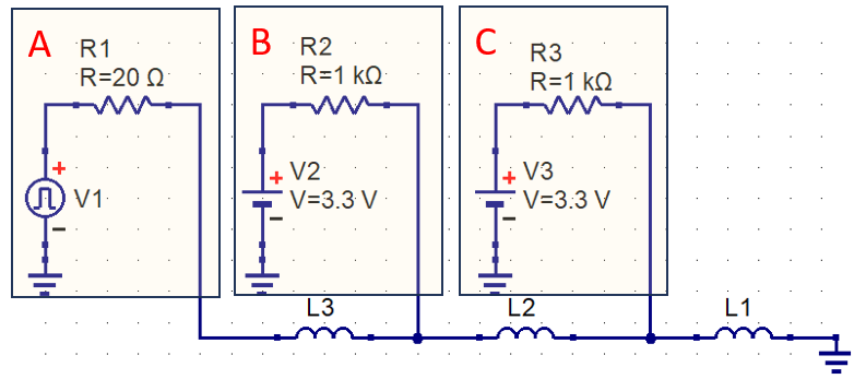
How you handle this common impedance is the fundamental difference between single-point ground and the ground plane.
Single-Point Ground — The Idea of Making the Common Impedance Zero
The idea behind single-point ground is simple: route each circuit’s GND wire separately and join them at only one place. This way circuits don’t share GND wiring, so no common impedance arises.
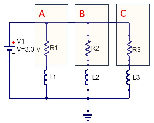
The effect is proven experimentally too. Compare a board where the GND wiring is deliberately given a common impedance with a board wired as single-point ground, and the single-point version has far less noise riding on GND.
The Weakness of Single-Point Ground — It Doesn’t Work at High Frequencies
However, single-point ground has a fundamental limitation.
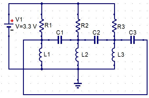
Route GND wires separately and long, and stray capacitance arises between the traces. At high frequencies they become electrically connected through this stray capacitance, so the GND wires you took the trouble to route separately end up “connected where you can’t see it.” In other words, at high frequencies the single-point ground stops working, and the long GND wires instead act as antennas that pick up noise.
Single-point ground is effective in the DC-to-low-frequency range (roughly below a few tens of kHz). It is still standard in audio circuits and low-frequency analog circuits, but it is not suited to digital or high-frequency circuits.
Ground Plane (Solid Ground) — The Idea of Driving the Impedance Right Down
The idea of the ground plane is the opposite of single-point ground. Rather than “making the common impedance zero,” it aims to “make it as small as possible.”
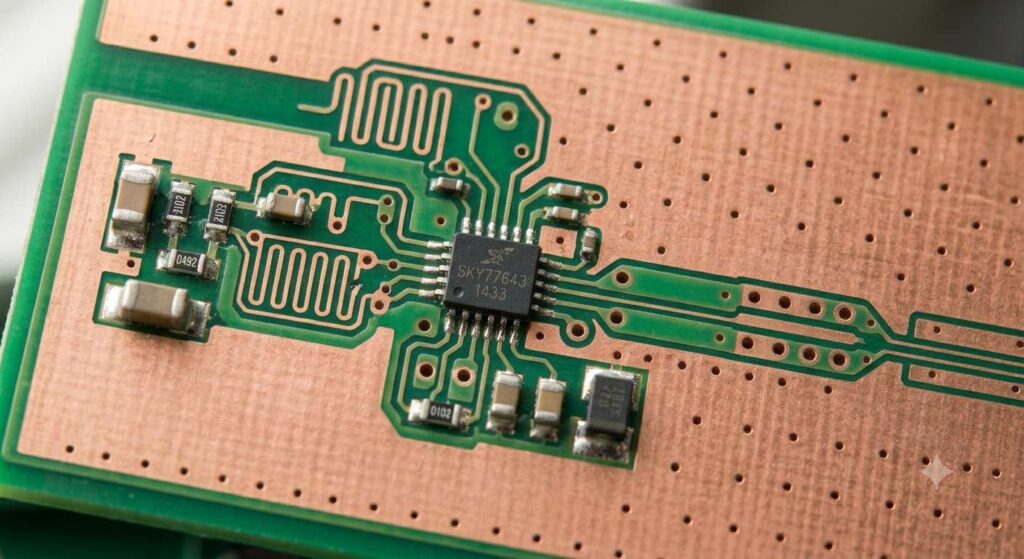
Cover an entire side of the board with GND copper (a solid pour) and the impedance is distributed over the whole surface, so wherever the current flows from, it is received at a very low impedance. The common impedance does not become zero, but it becomes small enough to cause no real harm.
The Ground Plane Works at High Frequencies Too
Unlike single-point ground, the ground plane is effective at high frequencies too. A planar copper sheet is less affected by stray capacitance and maintains a low impedance even as frequency rises. As a side benefit, it also shields the signal-routing layers.
On a 2-layer board it is standard to dedicate one side to the ground plane. On 4-layer or higher multilayer boards, the standard configuration assigns the power plane (solid V) and the ground plane to their own dedicated layers.
Comparing in uSimmics — Single-Point Ground vs. Ground Plane
Comparison at Low Frequency

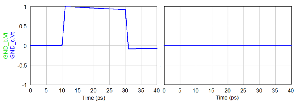
Comparison at High Frequency
The Approach Changes with Frequency — In Summary
| Single-point ground | Ground plane (solid ground) | |
|---|---|---|
| Principle | Eliminate the common impedance | Minimize the common impedance |
| Effective frequency | DC to low frequency (below tens of kHz) | Low to high frequency (broadly effective) |
| Suited circuits | Audio, low-frequency analog | Digital, high-frequency analog, mixed boards |
| Weakness | Nullified by stray capacitance at high frequency | Common impedance never reaches zero |
On modern digital boards, where clock frequencies reach tens to hundreds of MHz, the ground plane is the de facto standard. On the other hand, for low-frequency analog circuits such as audio amplifiers and instrumentation amplifiers, single-point ground is still a valid option.
What About Mixed Analog + Digital Boards?
On boards where analog and digital circuits coexist, a common approach is to split GND into an analog region and a digital region and connect them at only one place. This is a “split ground plane + single-point connection,” a compromise between the two. Choose the connection point where noise crossover is minimized, such as directly under the A/D converter.
Summary
- Single-point ground is a technique that eliminates common impedance and is effective for low-frequency analog circuits.
- At high frequencies its effect is lost to stray capacitance, so it is unsuited to digital circuits.
- The ground plane minimizes impedance across the whole surface and is broadly effective up to high frequencies.
- On modern digital boards the ground plane is standard. For low-frequency analog, single-point ground is also an option.
- For mixed boards, a “split plane + single-point connection” compromise is practical.
There is no “absolute right answer” in GND design. What matters is to check your circuit’s operating frequency and choose the appropriate technique.


Comment