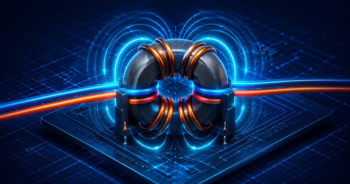
The term “common-mode noise” shows up constantly in EMC material and standards documents. Yet many people use it without ever getting a clear sense of “how it differs from normal mode” or “why common mode is easy to remove.”
In this article we organize the two modes starting from their definitions, and explain how a common-mode filter works using filter and equivalent circuits.
A Signal Always Travels on “Two Wires”
Let’s start with the basics. An electrical signal always travels by forming a loop with an outbound wire and a return wire. Even if only one line is drawn on the schematic, a ground line always exists as the shared return wire.
This fact — that “there are two wires” — is the starting point for thinking about common mode and normal mode.
Definitions of Normal Mode and Common Mode
Before the equations, let’s think with a concrete picture. Suppose two wires (D+ and D−) extend from an IC and carry a signal to a receiver some distance away.
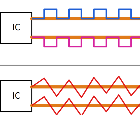
The signal the designer intentionally sends puts opposite waveforms on the two wires. The instant D+ rises to High, D− falls to Low. Subtract the two voltages at the receiver and you recover a clean signal with twice the amplitude. This is normal mode (differential mode).
External noise, on the other hand, rides on both wires at the same timing and in the same direction, because the two wires run parallel right next to each other. Exactly the same noise waveform is added to both D+ and D−. This is common mode (in-phase mode).
Expressed as voltage equations, this becomes the following. If the two wires (wire A and wire B) have voltages EA and EB relative to ground:
Normal mode (differential mode) is the voltage difference between the two wires:
EN = EA − EBThis is the voltage used as the “signal.” It is created by the pair of currents flowing in opposite directions on the outbound and return wires.
Common mode (in-phase mode) is the voltage riding in common on both wires:
EC = (EA + EB) / 2It is the mode in which both wires vary in the same direction by the same amount. In the figure above, the opposite-phase waveform corresponds to EN, and the same-phase overlapping noise corresponds to EC.
Restated in terms of current:
- Normal-mode current: the (round-trip) current flowing in opposite directions on the two wires
- Common-mode current: the current flowing in the same direction on both wires
The “Wanted Signal” Is Normal Mode; Noise Rides on Both
The signal a designer intentionally sends is always normal mode. You never send a signal in common mode (because the return path would become unstable).
Noise, on the other hand, rides on by itself. Both normal-mode noise and common-mode noise exist.
Here is the important difference:
- Normal-mode noise: same mode as the signal → indistinguishable from the signal. It can be removed with a filter if its frequency is far enough away, but in principle it is hard to remove.
- Common-mode noise: a different mode from the signal → it can be removed by exploiting the difference in mode.
The reason common-mode noise is “easier to deal with” is precisely that you can exploit this difference in mode.
When Common-Mode Noise Becomes Harmful
Because in common mode “the two wires move the same way,” in theory it should not affect a receiver that detects differentially. When a train runs at constant speed and a passenger jumps inside the train, they land back at the same spot — likewise, if the whole system varies uniformly, no error appears.
The problem arises when the magnitude of the common-mode voltage differs from place to place.
For example, if you connect two separated devices with a signal line and each is connected to earth at a different location, the earth potential differs slightly from place to place. This potential difference is applied between the two devices as a common-mode voltage, and it can turn into normal-mode noise.
The “Filter Difference” Between Common Mode and Normal Mode
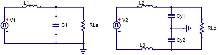
An ordinary low-pass filter (RC filter, LC filter) can only remove normal mode. Why? Because a bypass path for normal mode (the short path through the capacitor) is provided, but there is no path to bypass common mode.
A common-mode filter has a path to bypass common mode (a capacitor to ground).
The Common-Mode Choke (CMC)
The core component of a common-mode filter is the common-mode choke (CMC). It is an inductor with the two wires wound in the same direction on the same core:
- Normal-mode current: the two magnetic fluxes cancel each other → low inductance → the signal passes
- Common-mode current: the two magnetic fluxes add up → high inductance → it is blocked
Removal with a Differential Receiver
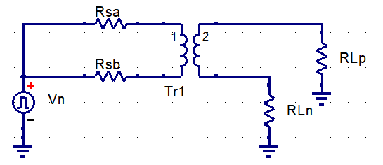
Another means besides a filter is the use of a differential receiver.
A differential receiver detects only the “difference voltage (normal mode)” of its two inputs. Because the common-mode component rides equally on both inputs, taking the difference cancels it.
The reason differential interface standards such as RS-422/RS-485 are strong over long distances and in noisy environments lies in this differential reception. Even between devices that do not share a ground, the signal can be received while cancelling common-mode noise.

Summary
- Normal mode is the “difference voltage” of the two wires; common mode is the “common voltage.”
- The wanted signal is normal mode. Noise rides in either mode.
- Common-mode noise can be removed by exploiting the difference in mode — that is why it is “easy to remove.”
- A common-mode filter (CMC + Y capacitors) presents high impedance only to common mode.
- A differential receiver cancels common mode and extracts only the signal.
Thinking about common mode and normal mode separately becomes the decision criterion for every kind of noise countermeasure — filter selection, board design, cable choice, and more.


Comment