Ferrite beads are widely used for noise suppression. You often see them on power rails and I/O lines, and in many cases they are treated as “just put one in for now.”
However,
- You can’t clearly explain why it worked.
- You don’t know why it didn’t work this time.
- The difference from an inductor is still vague.
If you keep using ferrite beads in that state, design decisions tend to become ad-hoc and person-dependent.
In this article, we整理 (organize) the question of “Why does a ferrite bead work?” using a minimal circuit model that can be reproduced in uSimmics (formerly QucsStudio). The short answer is: a ferrite bead works not because it is an inductor.
- Key takeaway
- A common misunderstanding: “Ferrite bead = inductor”
- A common baseline circuit to compare in uSimmics
- Waveform comparison: four cases with the same conditions
- What we learn from the four-waveform comparison
- Why not just use a resistor?
- Typical cases where a ferrite bead works / does not work
- Placement matters: where to put it
- Conclusion
Key takeaway
- A ferrite bead is not an ideal inductor.
- Its main purpose is not to “reflect noise and block it.”
- It works by dissipating high-frequency energy as loss (heat).
- That is why ringing is reduced and the waveform settles faster.
In other words, from an EMC perspective, a ferrite bead is a frequency-dependent lossy element. With this viewpoint, it becomes much easier to explain when it works, when it doesn’t, where to place it, and what alternatives (R or RC) can do.
A common misunderstanding: “Ferrite bead = inductor”
Ferrite beads are often described as “high impedance at high frequency” or “having an inductive component.” That is not wrong, but if you stop there, one key question remains.
If impedance is simply higher, why does ringing get smaller?
If “higher impedance” were the whole story, stronger reflection and a higher Q would tend to make ringing more pronounced. To clarify this, we first check the case of inserting an ideal inductor in uSimmics.
A common baseline circuit to compare in uSimmics
We use the following minimal circuit as a common baseline and compare four cases by swapping only the series element. The observation point is Vout (the top node of Cload).
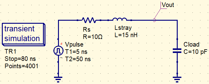
Example parameters
The following values are one example to make ringing and the effect of a ferrite bead easy to compare in uSimmics (formerly QucsStudio).
Adjust the rise time and component values to match your real circuit conditions.
| Item | Value | Intent |
|---|---|---|
| VPulse | 0 → 1 V | Clearly observe the step response |
| Tr / Tf | 1 ns | Example rise/fall time for clear comparison |
| Pulse width | 50 ns | Observe the post-edge behavior long enough |
| Rs | 10 Ω | Model of driver output resistance |
| Lstray | 15 nH | Parasitic inductance (trace/package) |
| Cload | 10 pF | Load + parasitic capacitance |
Transient settings (example)
- Stop time: 80 ns
- Max step: 20 ps (reduce further if the ringing is not resolved)
Note: These values are for education and visibility (to make ringing easy to see). For a real board, replace L/C/R with values that match your layout and components.
Waveform comparison: four cases with the same conditions
From here, we insert four waveform plots. For a fair comparison, save all plots with the same X/Y axis scale (this dramatically improves readability and credibility).
Waveform ①: No countermeasure (no series element)
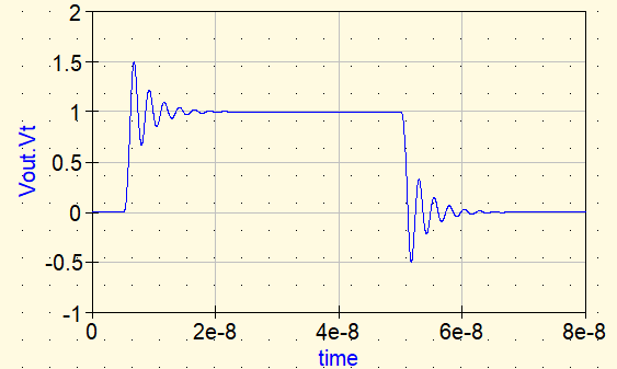
With no countermeasure, Vout shows overshoot right after the rising edge and then continues to ring. This is caused by resonance formed by Lstray and Cload. The lower the loss, the longer the oscillation persists.
Waveform ②: Insert an ideal L (trying to “stop it with an inductor”)
Next, we insert an ideal inductor as the series element.
- Lideal: 100 nH (example)
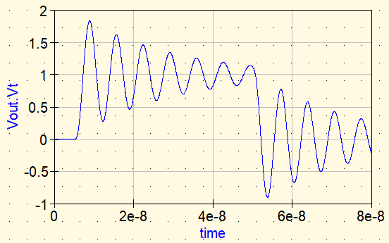
Ideal L: because it does not dissipate energy, ringing does not fundamentally stop (it may even become more pronounced).
It is tempting to think, “If impedance increases at high frequency, an inductor should stop the noise.” But an ideal inductor has no loss. Resonant energy remains in the circuit, so the ringing does not settle quickly (in some cases the Q effectively increases).
This is the key point: it is not “higher impedance makes it stop.” Without loss, it is hard for ringing to die out.
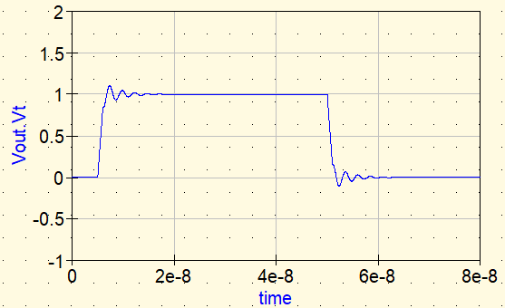
Waveform ③: Insert an ideal R (what happens when we add loss?)
Now we insert an ideal resistor as the series element.
- Rideal: 10 Ω (example)
With a resistor, the ringing is clearly damped. The reason is simple: oscillation energy is dissipated as heat in the resistor.
So the “real reason” ringing stops is not the impedance height but loss (R).
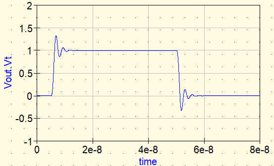
Waveform ④: Insert a ferrite bead
Finally, we run a simulation using a real ferrite bead. Here, we insert the ferrite bead as an S-parameter (2-port) component in series and compare it with ideal elements.
- Ferrite bead used: BLM03AG601SN1 (Murata)
- S-parameter (.s2p): available from Murata’s website
Because a ferrite bead has frequency-dependent behavior, using S-parameters lets us check a more realistic response in the time domain.
Ferrite (S-parameter): little effect at low frequency, but increasing loss at high-frequency components makes the ringing settle faster.
When the ferrite is inserted using S-parameters, the ringing is damped similarly to the ideal-R case. However, the crucial difference from a resistor is frequency dependence.
A resistor introduces loss uniformly from DC, while a ferrite bead increases loss mainly in the frequency range where it is intended to work. As a result, energy is dissipated mainly from the high-frequency components contained in the edge, and the ringing settles faster while minimizing the impact on DC and low-frequency components.
What we learn from the four-waveform comparison
- No countermeasure: resonance appears directly.
- Ideal L: hard to settle (no loss).
- Ideal R: settles (has loss).
- Ferrite bead: settles (loss increases in the relevant frequency range).
So a ferrite bead works not because it is an inductor, but because it provides loss. More specifically, its strength is that it can produce loss selectively by frequency.
Why not just use a resistor?
It is natural to ask, “Then why not just add a resistor?” Indeed, adding a resistor can stop ringing.
But a resistor has drawbacks:
- Voltage drop even at DC
- Higher power loss
- More impact on the intended signal or power quality
In contrast, a ferrite bead has little impact at DC/low frequency and acts as loss where needed at high frequency. That is why a ferrite bead can be thought of as a “resistor that works only where you want it to”.
Typical cases where a ferrite bead works / does not work
Cases where it tends to work
- High-frequency ringing on power rails
- Noise generated by fast digital edges on I/O lines
- When radiated emissions are driven mainly by high-frequency components
Cases where it may not work (or can get worse)
- The dominant noise is low-frequency and does not overlap the bead’s lossy region
- You create a new resonance after the bead
- The return path (GND) is far, so energy is not dissipated as intended
Placement matters: where to put it
A ferrite bead is not a “wall.” More precisely, it is an exit for dumping energy.
Therefore, it works best when placed:
- Close to the noise source
- Right before the point where you want to stop high-frequency energy from spreading
- Where the return path (GND) is short and well-defined
Placing it with these points in mind maximizes the effect.
Conclusion
A ferrite bead works not because it is an inductor, but because it dissipates high-frequency energy as loss. That is why an ideal inductor does not stop ringing, while a resistor or a ferrite bead (both lossy elements) helps the waveform settle faster.
At the same time, a ferrite bead does not work in every situation. If the bead’s loss characteristic does not overlap the ringing frequency range, the waveform can look almost the same as the “no countermeasure” case. Placement and the return path also strongly affect how (and where) energy is dissipated.
By comparing circuits in uSimmics, you can see from the waveforms that it is not simply “high impedance” that helps, but where and at what frequencies the energy is being damped. This kind of visualization is a practical way to understand ferrite beads not as a “parts-bin habit,” but as a component you can use with clear reasoning.
After “countermeasure parts”, the next topic is coupling (crosstalk), which often doesn’t show up clearly on schematics. We’ll capture where capacitive coupling and inductive coupling come from using an equivalent circuit.
▶ Next: What Is Crosstalk? The Hidden Coupling That Doesn’t Appear on Schematics

Comment