Getting Started with Digital Simulation in Qucs Studio
Qucs Studio is a powerful tool that supports digital simulation. This article explains the content listed in the Help file in an orderly fashion.
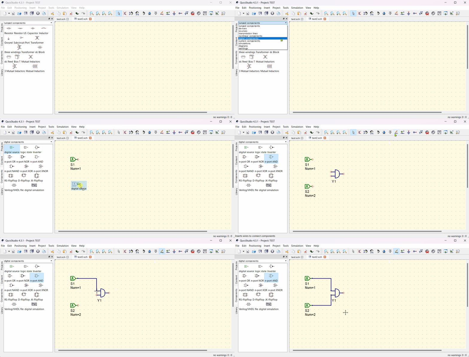
Step 1: Selecting Digital Components
- Open Qucs Studio and select “Digital Components” from the component tab on the left.
- To create a truth table for a simple logical AND cell, choose the necessary digital components and assemble the circuit.
Let’s make a simple logic circuit with two inputs and one AND gate.
Place the “digital source” and “n-port AND” from the digital component onto the schematic and wire them up.
Step 2: Naming Nodes
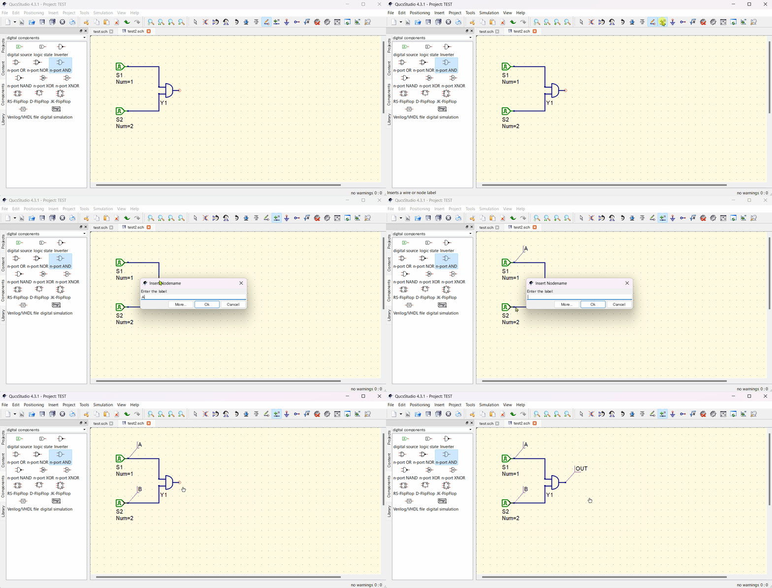
- Name the nodes on the schematic where you want to check the logic. Use “insert wire Label” to do this.
digital source1: A
digital source2: B
Output: OUT
Step 3: Placing Simulation Block
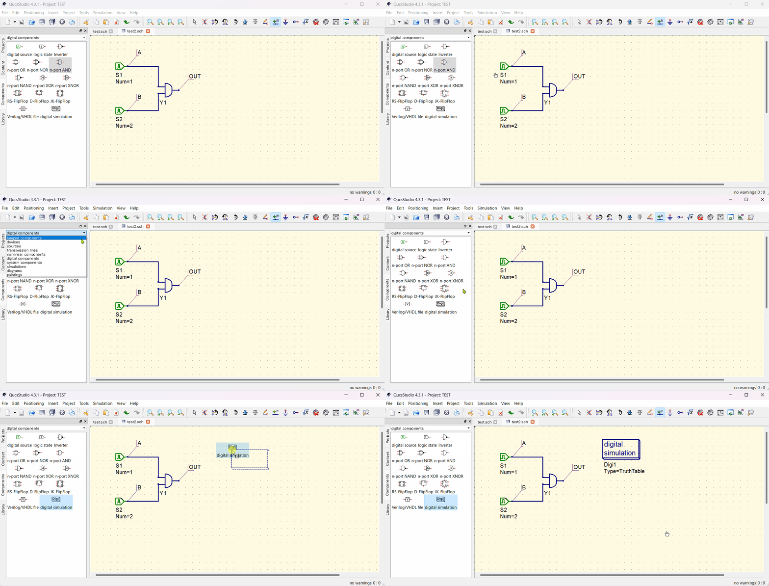
- Find and place the digital simulation block from digital components.
Step 3: Running the Simulation
- Press the “Simulate” button to execute the simulation, and the truth table will be displayed.
Step 4: Displaying the Truth Table
- By inserting the “Output” variable into the truth table diagram, the truth table of a two-port AND cell will be displayed.
Step 5: More Complex Digital Simulations
- Beyond truth tables, it’s also possible to apply arbitrary signals to a circuit and see the output signal in a timing diagram.
- To do this, change the “Type” parameter of the simulation block to “TimeList” and set up the input signals for simulation as follows (please Simulate again after changing settings):
S1: 1nsec/1nsec S2: 2nsec/2nsec - To check the results in waveform, place a “Timing Diagram” from diagrams.
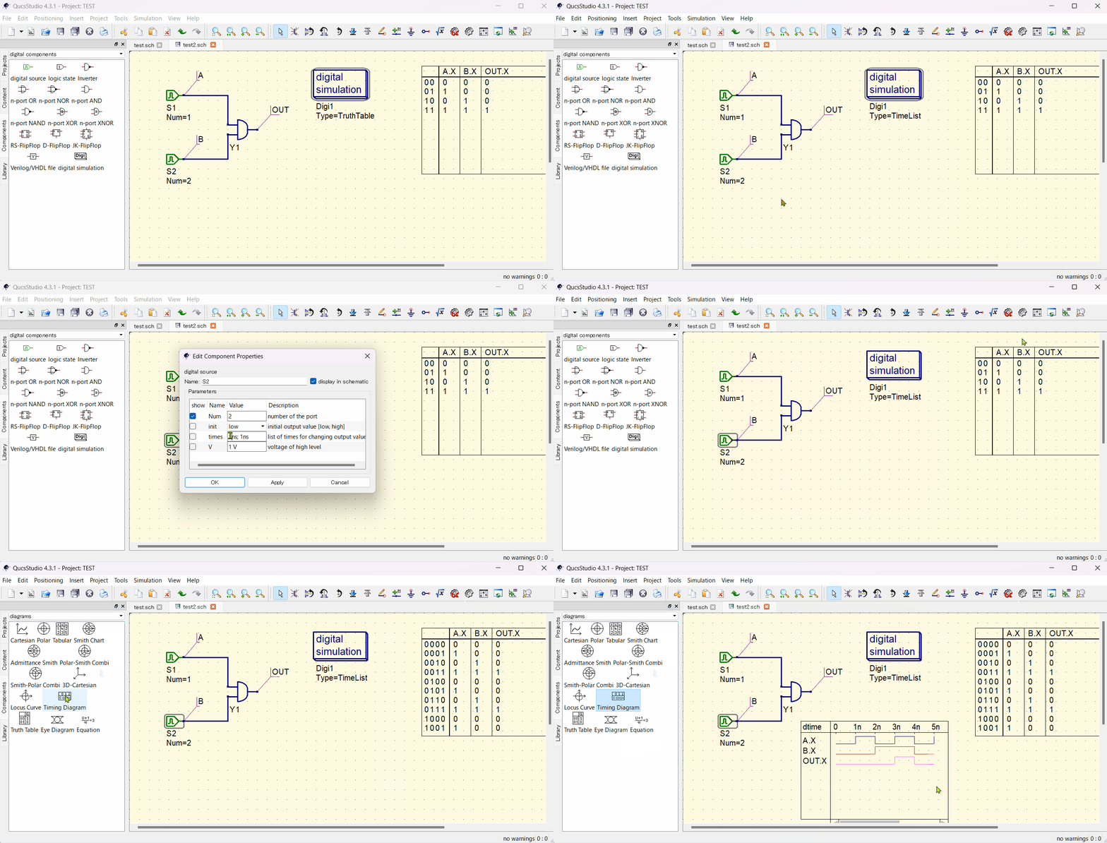
Through these steps, you can learn the basic methods for starting digital simulation in Qucs Studio. From creating simple truth tables to conducting more advanced digital simulations, Qucs Studio caters to a wide range of needs.
📌 See the recommended reading order (Roadmap)
➡️ Next: Subcircuits


Comment