
This time, we will talk about the very important “parametric analysis” in electronic circuit design. By using this method, you can investigate in detail the behavior of a circuit when specific parameters are changed. It is especially useful for optimization and understanding performance during the design stage. Let’s take a look at the specific steps using QucsStudio.
What is Parametric Analysis?
Parametric analysis is a method of changing specific parameters (e.g., resistance, capacitance, power supply voltage) in a circuit or system and observing their effects. It is widely used for the following purposes:
- Evaluation of Parameter Effects: Clarify the impact of individual parameters on the overall circuit operation.
- Optimization: Find the optimal parameter settings to maximize or minimize specific performance indicators (e.g., output power, efficiency, bandwidth).
- Robustness Evaluation of Design: Assess the sensitivity of the system to parameter variations and errors, confirming the robustness of the design.
Steps for Parametric Analysis with QucsStudio
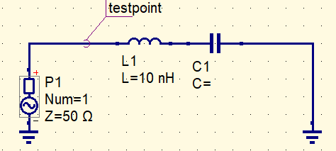
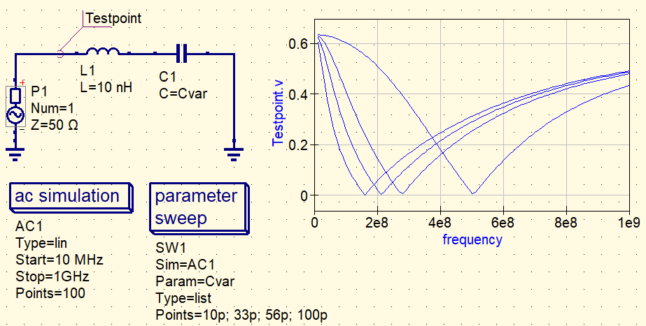
Here, we will explain the steps to graph the voltage changes when the capacitance of a capacitor is varied, using a circuit where an inductor and a capacitor are connected in series as an example.
1. Creating the Circuit
- Start QucsStudio: Launch QucsStudio and create a new project.
- Create the Circuit Diagram:
- Select “Inductor” and “Capacitor” from the “Components” tab and place them in the workspace.
- Connect the inductor and capacitor in series.
- Set the inductance value to a fixed value, here we use 10nH.
- Place the power source and ground to complete the circuit.
- Set a “testpoint” before the inductor to measure the voltage.
2. Setting Parameters
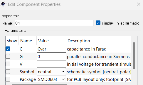
- Set Variables: Double-click the properties of the capacitor and set the variable name “Cvar” in the field for capacitance (C). This allows the capacitance to be treated as a variable, which can be changed during simulation.
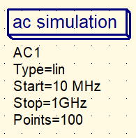
2.Setting AC Simulation: Add the “AC Simulation” block to the circuit from the “Simulations” tab. Then, set the following parameters:
- Set Frequency Range: Specify the start and end frequencies of the simulation. For example, set the range from 10MHz to 1GHz.
3. Setting Parametric Analysis
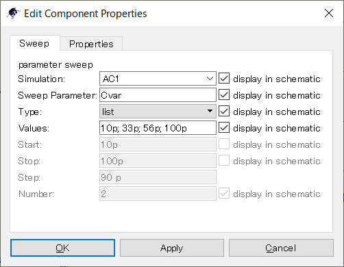
- Add Parameter Sweep: Add the “Parameter Sweep” block from the “Simulations” tab.
- Select “Cvar” as the parameter to sweep, and set the sweep range and step count.
・Linear: Increases frequency at equal intervals.
・Logarithmic: Increases frequency logarithmically.
・List: Sets a specific list of frequencies.
Here, we will use List to simulate capacitors with 10p, 33p, 56p, and 100pF.
・Type: list
・Value: 10p; 33p; 56p; 100p
4. Running the Simulation
- Start the Simulation: Click the “Simulate” button to run the simulation.
- Plot the Results: Add a “Cartesian Plot” for displaying the results (usually added automatically) and plot the voltage changes of testpoint.v.
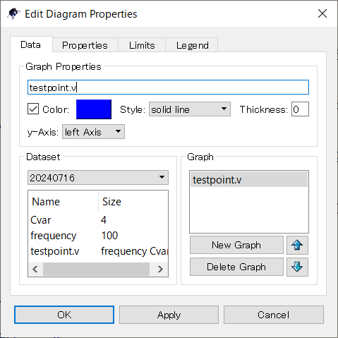
5. Evaluating the Results
- Analyze the Graph: Analyze the obtained graph to evaluate the effect of the capacitor’s capacitance on the voltage. From this example, the resonance frequency of the LC series circuit can be visualized.
- Determine the Optimal Capacitance Value: Re-run the simulation with different conditions if necessary to determine the optimal capacitance value.
Conclusion
Parametric analysis is an essential method for optimization and performance evaluation during the design stage. By using QucsStudio, you can easily change circuit parameters and visually evaluate their effects. Use the steps outlined in this guide to try parametric analysis on various circuits.
📌 See the recommended reading order (Roadmap)
➡️ Next (recommended): MLCC basics (how capacitors behave in real circuits)


Comment