Let’s introduce an efficient method to import S-parameter files using Qucs Studio. This process is crucial for improving the accuracy of RF circuit simulations.
What are S-Parameters?
S-parameters (scattering parameters) represent numerical values that describe the behavior of RF (radio frequency) circuits, indicating the reflection and transmission characteristics of the circuit at high frequencies. Each parameter represents the response at other ports when a signal is applied to a specific input port of the circuit. For example, S11 represents the reflection coefficient at the input port, and S21 represents the transmission coefficient between different ports.
S-parameter files indicate the number of ports by their extension. For instance, .s1p represents a one-port circuit, while .s2p represents a two-port circuit. These files are also known as ‘Touchstone format’ and are widely used in analyzing and designing high-frequency circuits.
S-parameters can be outputted using circuit simulators like Qucs or network analyzers, or by measuring actual circuits. Additionally, manufacturers of high-frequency electronic components may provide S-parameters for their products.
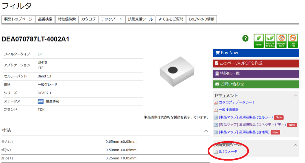
In this example, we will use TDK’s low-pass filter ‘DEA070787LT-4002A1’. The S-parameter can be downloaded from TDK’s website. Select the technical support tool on the right side of the screen.
The file name is ‘dea070787lt-4002a1.s2p’.
Next, we will explain how to import this downloaded S-parameter into QUCS.
Step 1: Placing Components
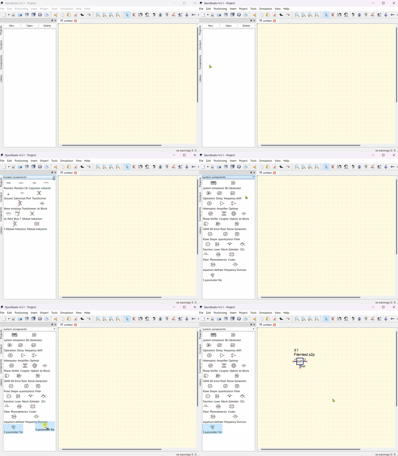
Open QucsStudio, select the ‘Components’ tab from the left menu.
Click on the ‘system components’ option.
Then select ‘S parameter file’, and place it on the circuit diagram by dragging and dropping or clicking.
Step 2: Editing Data
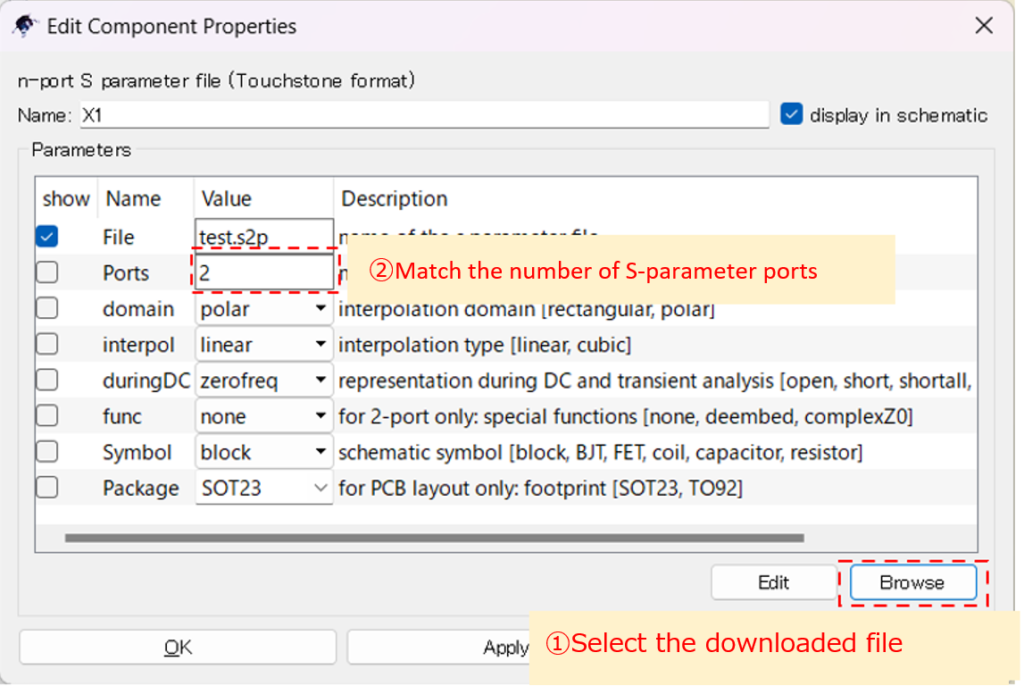
To handle S-parameter files in QucsStudio, first double-click the ‘S parameter file’ component placed on the circuit diagram to open the property window. Then, use the ‘Browse’ button in the property window to select the required Touchstone file. In the same window, check the number of ports in the ‘Ports’ section and make necessary changes, then apply them with the ‘Apply’ button. This completes the setting of the S-parameter file in QucsStudio.
Step 3: Creating Circuit Diagram and Setting Simulation Conditions
In preparing for circuit simulation in QucsStudio, first select ‘Power Source’ from the ‘Sources’ menu and place it on the circuit diagram. Next, connect the necessary components together, and connect each element to GND (ground) to establish a reference potential. Finally, select ‘S-parameter simulation’ from the ‘Simulations’ menu and place it on the circuit diagram.
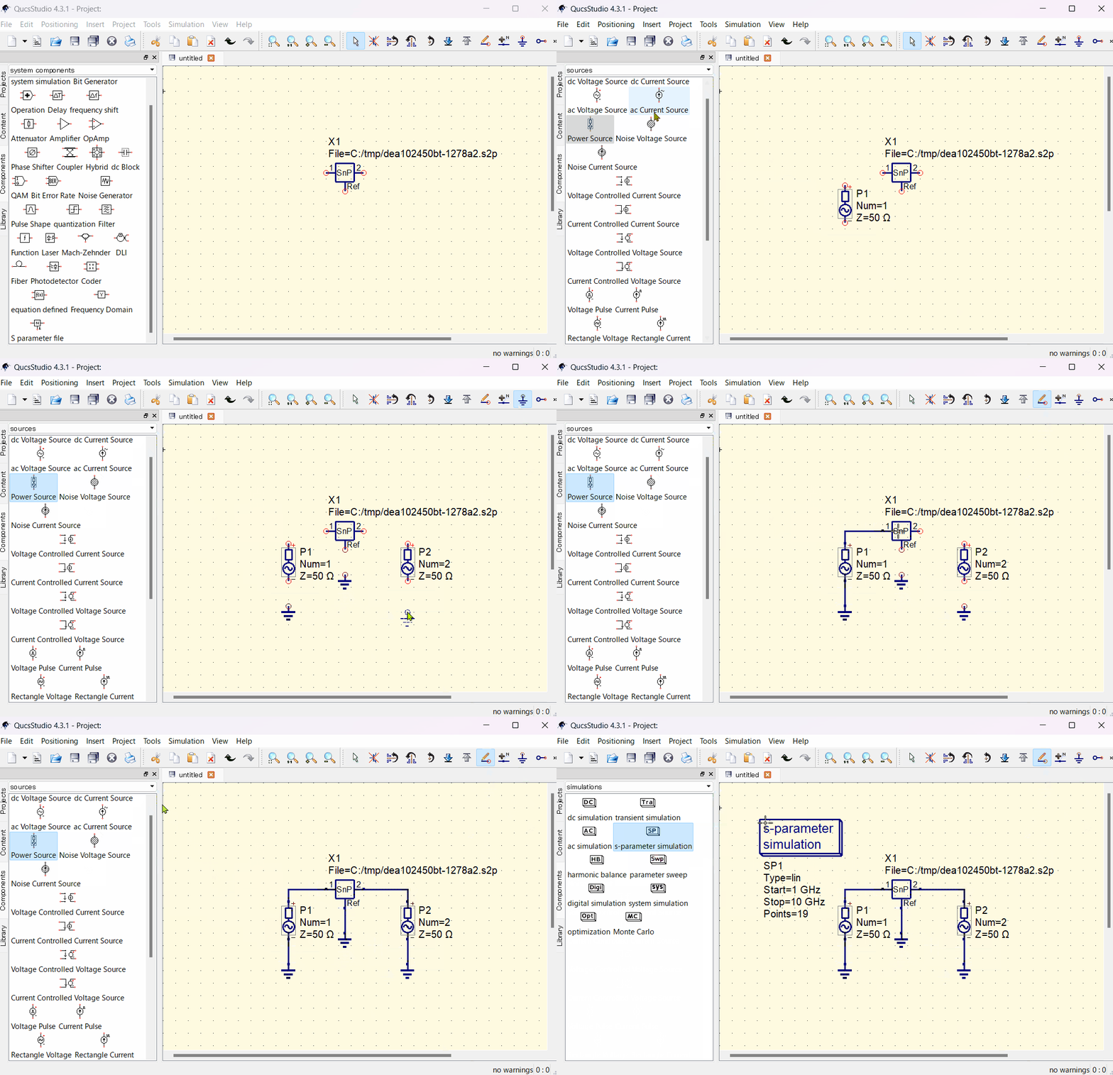
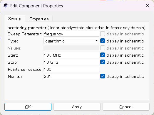
Set the simulation settings as follows:
- Graph Type: Logarithmic graph
- Frequency Range: 100MHz to 10GHz
- Measurement Points: 201 points (10 points/1dB)
Step 4: Running the Simulation
Before running the simulation in QucsStudio, first set the file name for the simulation. This is done on the circuit diagram editor, and the file name is used to save the results of the simulation. Once the file name is set, click on the gear icon in the upper right of the screen to start the simulation. This action executes the simulation based on the set parameters, producing the results.
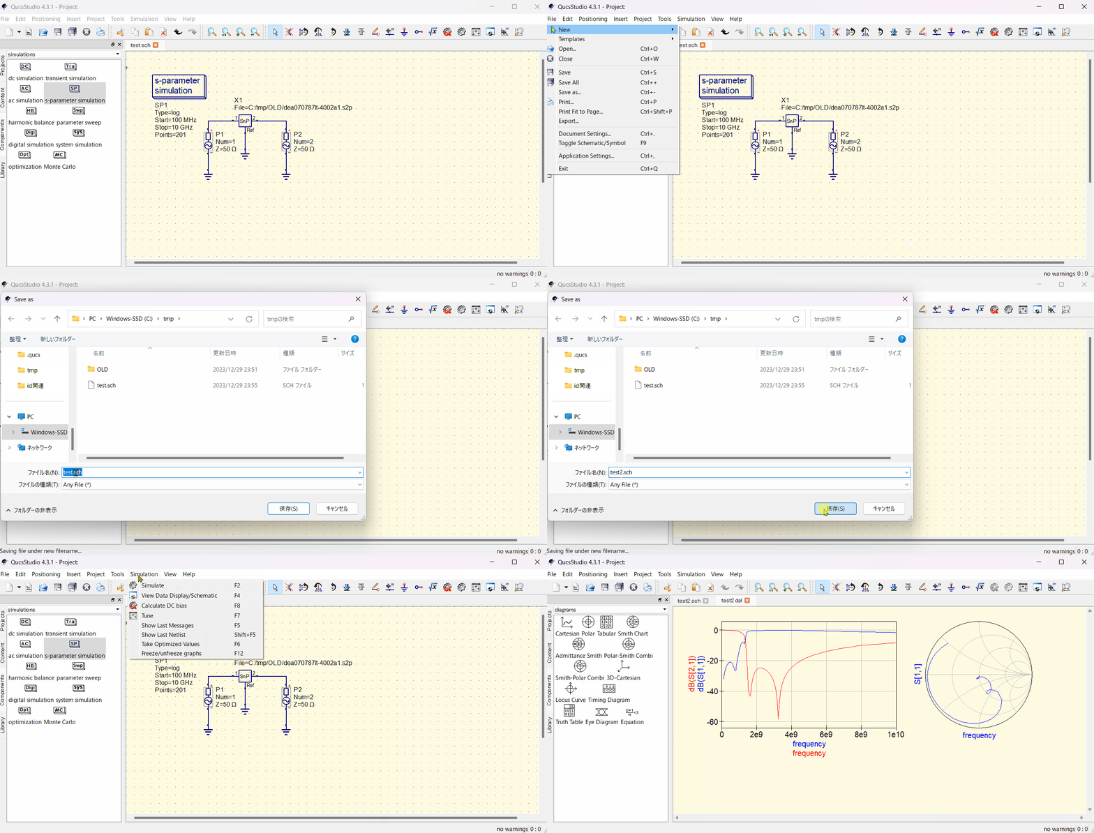
By importing S-parameter files into Qucs Studio and running simulations, you can display S-parameters graphically and evaluate circuit characteristics. Mastering this process is essential as accurate data importation is vital for effective simulations.
📌 See the recommended reading order (Roadmap)
➡️ Next: Smith Chart Basics


Comment