When calculating stripline characteristic impedance in uSimmics (formerly QucsStudio), you may notice a gap between the theoretical result and measured values on actual boards. One common cause is the change in conductor cross-section caused by etching undercut during PCB fabrication. This article explains the mechanism behind the phenomenon and provides a practical correction workflow.
What You’ll Learn
- How the subtractive PCB process creates etching undercut
- Why a trapezoidal conductor cross-section raises stripline characteristic impedance
- How to calculate a corrected effective trace width using the trapezoid average
- How to enter the corrected value into uSimmics (formerly QucsStudio) and re-run the calculation
- How to feed the correction back into your design to hit the target impedance at first pass
1. Stripline Basics and Characteristic Impedance
A stripline is a transmission line structure in which a signal conductor is embedded in the inner layer of a PCB and sandwiched between two ground planes above and below. This geometry suppresses electromagnetic radiation and makes it well suited for high-frequency (RF/microwave) signal routing.
Characteristic impedance is determined by four physical parameters:
- Trace width W
- Substrate relative permittivity εr
- Dielectric thickness H
- Conductor thickness T
Entering these into the Transmission Line Calculator in uSimmics (formerly QucsStudio) gives a theoretical characteristic impedance. However, the actual fabrication process introduces deviations that the theory alone cannot capture.
2. The Subtractive Process and Etching Undercut
What Is the Subtractive Process?
The most widely used PCB patterning method is the subtractive process. A copper-clad laminate is etched — copper is dissolved chemically — everywhere except where a photoresist mask protects the desired circuit pattern. The technique is cost-effective and highly suitable for high-volume production.
How Etching Undercut Occurs
Etchant is intended to attack copper from above, but in practice it also etches laterally into the sides of the conductor. This lateral dissolution is called etching undercut.
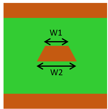
When etching undercut occurs, the conductor cross-section changes from the intended rectangle to a trapezoid:
- Top width W2 (resist side): close to the designed value
- Bottom width W1 (substrate side): smaller than designed due to lateral etching
This shape change alters the effective cross-sectional area and width of the signal trace, directly affecting characteristic impedance.
3. How a Trapezoidal Cross-Section Raises Characteristic Impedance
Standard impedance formulas assume a rectangular conductor with a uniform width. When etching undercut produces a trapezoidal cross-section, the effective trace width is reduced. The consequence:
Effective trace width decreases → characteristic impedance increases above the designed value.
This can be understood through the relationship between capacitance and inductance. Characteristic impedance is given by:
Z₀ = √(L/C)
where L is inductance per unit length and C is capacitance per unit length. A narrower trace reduces C, which raises Z₀.
In practice, a stripline designed for 50 Ω can measure 55–60 Ω after fabrication due to etching undercut. This error can exceed the typical impedance tolerance of ±10%, making the effect non-negligible from a signal-integrity standpoint.
4. Correction Calculation Procedure
Step 1: Obtain the As-Built Dimensions
PCB fabrication specifications and manufacturing reports from your supplier will include the etching undercut value. Use this information to determine the actual top width W2 and bottom width W1.
A common rule of thumb for the subtractive process is that pattern width is roughly 10% smaller than the designed value. For example:
- Designed pattern width: 100 μm
- Actual top width W2: 100 μm (resist side, close to design)
- Actual bottom width W1: 80 μm (substrate side, reduced by etching)
Step 2: Calculate the Effective Width (Trapezoid Correction)
Use the average of the top and bottom widths as the effective trace width:
W_eff = (W1 + W2) / 2
For the example above:
W_eff = (80 + 100) / 2 = 90 μm
Using W_eff = 90 μm in the impedance calculation significantly improves agreement with measured values.
Step 3: Re-calculate in uSimmics (formerly QucsStudio)
- Open the Transmission Line Calculator in uSimmics (formerly QucsStudio).
- Select Stripline from the choice drop-down.
- Enter the substrate parameters under Properties.
- In Dimensions, set W (trace width) to the corrected effective width W_eff.
- Check the resulting characteristic impedance.
Comparing the result before correction (W = 100 μm) and after correction (W_eff = 90 μm) lets you quantify the impedance impact of etching undercut.
Step 4: Feed the Correction Back into the Design
To achieve the target impedance of 50 Ω in the as-built board, you need to design the pattern wider, compensating for the material that will be removed by undercut:
- Enter Z₀ = 50 Ω into uSimmics (formerly QucsStudio) to calculate the required ideal trace width W_ideal.
- Apply the undercut correction factor (for example, 10%) to obtain the design width:
W_design = W_ideal / (1 − undercut rate)
- Use the corrected W_design in your PCB design files submitted to manufacturing.
5. Additional Factors That Affect Impedance Accuracy
| Factor | Effect | Mitigation |
|---|---|---|
| Etching undercut | Impedance increase | Trapezoid correction (use average width) |
| Dielectric constant manufacturing variation | Impedance spread | Include design margin |
| Conductor thickness variation | Minor impedance shift | Confirm with fabricator’s spec sheet |
| Temperature-dependent permittivity | Impedance drift over operating temperature range | Select high-Tg substrate material |
High-frequency PCB design requires considering all of these factors together when setting impedance targets and tolerances.
6. Summary
The Transmission Line Calculator in uSimmics (formerly QucsStudio) is a powerful tool for stripline impedance design, but real PCB fabrication via the subtractive process introduces etching undercut that shifts the actual impedance away from the theoretical value. Applying the trapezoid correction — using the average of the top and bottom trace widths as the effective width — substantially improves calculation accuracy. Obtaining as-built dimension specifications from your fabrication supplier and integrating the correction into your PCB design flow are essential steps toward reliable impedance control.
Related Articles
- Stripline Characteristic Impedance Calculation Guide Using uSimmics (formerly QucsStudio)
- Optimizing Footprint Patterns for Impedance Continuity in RF PCB Design with uSimmics (formerly QucsStudio)
- Characteristic Impedance Calculation for Hybrid PCBs with Mixed-Dielectric Layers Using uSimmics (formerly QucsStudio)
- Automatic Impedance Matching in uSimmics (formerly QucsStudio)
- Installing and Configuring uSimmics (formerly QucsStudio)
Comment