
Steps for Creating Models
In QucsStudio, there are three main approaches to model creation: equation components, VerilogA models, and C++ models. Each of these has its own characteristics and advantages while sharing the common goal of building accurate simulation models.
1. Equation Components
Equation components are very suitable for defining the behavior of components using simple formulas. This method is intuitive, accessible, and allows for quick integration of basic electrical characteristics or linear models into simulations. It involves directly entering mathematical equations and observing the results in real-time, making it ideal for beginners or basic simulation needs.
2. VerilogA Models
VerilogA models are suited for modeling components with specific nonlinear characteristics or frequency-dependent properties. VerilogA is a hardware description language for analog and mixed-signal systems, offering enough flexibility to represent complex behaviors or custom devices. This approach allows for a more detailed definition of behavior and the emulation of specific physical phenomena, suitable for intermediate to advanced-level simulations.
3. C++ Models
C++ models are particularly suitable when advanced mathematical algorithms or computational processing is required. Using the C++ language allows for highly customized and efficient computations, meeting the needs of the most complex simulation requirements. This approach enables the use of existing libraries and the incorporation of advanced numerical analysis techniques, providing the most flexible and powerful construction of simulation models.
Commonalities and Choosing an Approach
These three approaches share the common objective of enabling the construction of accurate simulation models in QucsStudio. The choice depends on the simulation goal, required accuracy, developer skill level, and project complexity. Starting with simple models and moving to more advanced approaches as needed offers flexibility to meet various simulation needs. Each approach serves as a tool to provide optimal solutions for specific problems faced by users.
Using Equation Components
- Example of a Simple Resistance Model:
- Use the “Equation Component” to define the behavior of resistance for a specific voltage.
- Example: Calculate the current
Iusing the formulaI = V/R, whereVis voltage andRis resistance value.
Step 1: Adding an Equation Component
Find the “nonlinear components” section in the “Components” panel on the left side of the main window. Locate the “Equation Component,” click and drag it to drop it into the work area (schematic).
Step 2: Defining the Equation
Double-click the equation component to open the property editor.
Enter the equation I = V/R that defines the resistance model in the “Equation” field. Here, I represents current, V represents voltage, and R represents resistance value.
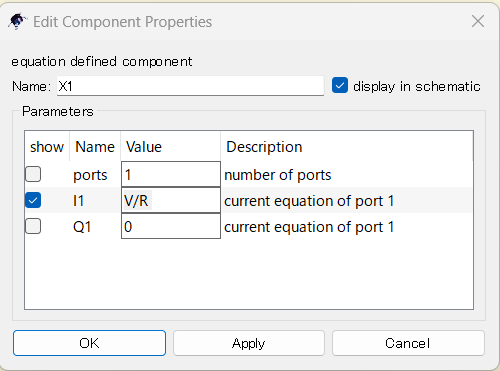
You can enter additional equations to define the values for V and R as needed. For example, you can set specific values like V = 5 (voltage of 5 volts) and R = 100 (resistance of 100 ohms).
Step 4: Running the Simulation
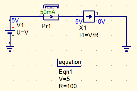
Before running the simulation, add voltage source (V) and ground (GND) components to complete the circuit.
Click the “Simulation” button to start the simulation. Once the simulation is complete, the results will be displayed. You can check the value of current I and verify that the equation I = V/R has been correctly calculated.
Creating VerilogA Models
- Example of a Custom Transistor Model:
- Create a transistor model with specific nonlinear characteristics or frequency properties using VerilogA language.
- Example: Describe a unique current-voltage relationship to replicate specific behavior.
Step 1: Creating a VerilogA File
Use any text editor to write a .va file containing your VerilogA code.
For example, use the VerilogA language to describe the transistor’s current-voltage relationship.
Here is a basic code example for the current-voltage relationship.
module CustomTransistor(n1, n2, n3);
inout n1, n2, n3;
electrical n1, n2, n3;
parameter real Vth = 0.7; // Threshold voltage
parameter real K = 1.0e-3; // Transistor constant
analog begin
if (V(n2, n3) > Vth) begin
I(n1, n2) <+ K * (V(n2, n3) – Vth)^2;
end else begin
I(n1, n2) <+ 0;
end
end
endmodule
- This code defines a transistor with three terminals: n1 (base), n2 (collector), n3 (emitter).
Vthis the transistor’s threshold voltage, andKis a constant defining the transistor’s characteristics.- The
analog begin ... endblock defines the formula for calculating the collector current.
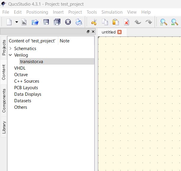
Save the text file with the extension .va and copy it to the folder of the project using this model in QucsStudio.
Once properly placed, you can access the .va file from the “Content” on the left side of the main window.
Step 2: Placing the VerilogA Model
You can add the transistor model described in VerilogA to your schematic.
Select the Verilog model you want to use, and you can place it on the schematic by moving the cursor over it.
Now, you can use the created transistor model for simulation.
Creating C++ Models
This article does not cover it, but you can create models using C++ code similar to the VerilogA description.
Summary
This guide introduced how to create user models in QucsStudio and utilize them in simulations. To achieve accurate simulation results, it’s important to properly adjust the model parameters and verify them against the actual device characteristics.


Comment