The Qucsattenuator tool bundled with uSimmics (formerly QucsStudio) lets you automate attenuator design — from topology selection and resistance calculation to exporting a ready-to-simulate schematic. This guide walks through the complete workflow.
- What You’ll Learn
- What Is Qucsattenuator?
- Step 1: Launching Qucsattenuator
- Step 2: Attenuator Topology and Parameter Setup
- Step 3: Computing Resistor Values
- Step 4: Rounding to Standard E-Series Values
- Step 5: Pasting the Result into a Schematic
- Step 6: Verifying with Simulation
- Important Notes
- Related Articles
What You’ll Learn
- How to launch Qucsattenuator and navigate its interface
- Attenuator topologies (T-type, Pi-type, Bridged-T, L-type) and how to choose among them
- How to calculate resistor values for a target attenuation
- How to round theoretical values to standard E6/E12 component series
- How to paste the generated circuit directly into a uSimmics (formerly QucsStudio) schematic
What Is Qucsattenuator?
Qucsattenuator (qucsattenuator.exe) is an attenuator synthesis tool included in the uSimmics (formerly QucsStudio) installation package. An attenuator is a passive circuit element that reduces signal level by a fixed amount. Attenuators are used throughout RF and microwave design for impedance matching, over-input protection, and calibrating measurement setups.
With Qucsattenuator, you can instantly compute resistor values for any supported topology and export a simulation-ready schematic — no manual calculation required.
Step 1: Launching Qucsattenuator
- Open the uSimmics (formerly QucsStudio) installation directory.
- Double-click
qucsattenuator.exeto launch it. - Alternatively, in the uSimmics (formerly QucsStudio) menu bar select Tools → Attenuator synthesis.
- The Qucsattenuator main window appears.
Step 2: Attenuator Topology and Parameter Setup
2-1. Selecting a Topology
Use the Choice drop-down menu to select a circuit topology. The main options are:
| Topology | Description |
|---|---|
| T-type | Two series resistors and one shunt resistor. Suitable for unbalanced circuits. |
| Pi-type | Two shunt resistors and one series resistor. Suitable for unbalanced circuits. |
| Bridged-T | Variant of the T-type. Advantageous under specific design constraints. |
| L-type | Asymmetric topology used when impedance transformation is required. |
Choose the topology that best matches your circuit’s impedance requirements and physical implementation constraints.
2-2. Entering the Attenuation Value
Type the target attenuation in dB into the Attenuation field.
2-3. Setting the Impedance
Enter the input/output impedance (typically 50 Ω) in the Impedance field.
Step 3: Computing Resistor Values
Once parameters are entered, Qucsattenuator immediately calculates and displays the resistor values (R1, R2, R3, etc.).
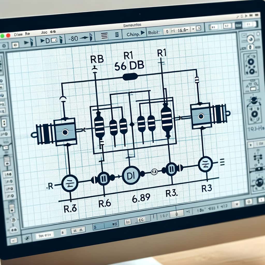
Design example: T-type attenuator, 6 dB attenuation, 50 Ω impedance
- Select T-type from the Choice menu.
- Enter
6(dB) in the Attenuation field. - Enter
50(Ω) in the Impedance field. - The following theoretical values are displayed automatically:
| Component | Theoretical Value |
|---|---|
| R1 | 16.6 Ω |
| R2 | 66.9 Ω |
| R3 | 16.6 Ω |
Step 4: Rounding to Standard E-Series Values
The calculated values are theoretical and will generally not match commercially available standard components (JIS/IEC E-series).
For real component selection, click the E6 or E12 button at the bottom of the screen. The tool rounds each theoretical value to the nearest standard value in the selected series.
- E6 series: 6 nominal values per decade. Typically ±20% tolerance components.
- E12 series: 12 nominal values per decade. Typically ±10% tolerance components.
For designs requiring tighter accuracy, consult E24 or E96 series component tables separately.
Step 5: Pasting the Result into a Schematic
Qucsattenuator can paste the computed circuit directly into the uSimmics (formerly QucsStudio) schematic editor.
5-1. Copying to the Clipboard
Two buttons appear at the bottom of the window:
| Button | Action |
|---|---|
| Put Circuit into Clipboard | Copies the schematic data only. |
| Into Clipboard including Simulation | Copies the schematic together with an S-parameter simulation setup. |
Choose the option appropriate for your workflow.
5-2. Pasting into uSimmics (formerly QucsStudio)
- Open or create a new schematic in uSimmics (formerly QucsStudio).
- Press Ctrl + V in the schematic editor.
- The attenuator circuit is inserted at the cursor position.
- If you used Into Clipboard including Simulation, the circuit is immediately ready to simulate.
Step 6: Verifying with Simulation
Run a simulation on the pasted schematic to confirm the attenuator’s frequency response (S21, S11, etc.).
- Add an S-parameter Simulation component to the schematic (already included if you used the simulation-inclusive clipboard option).
- Set the frequency range and number of points.
- Run the simulation and check that S21 matches the target attenuation and that S11 is sufficiently low.
Important Notes
- The resistor values produced by Qucsattenuator are based on ideal resistors. In real high-frequency circuits, chip resistors introduce parasitic inductance and capacitance. For GHz-band designs, complement this tool with electromagnetic field simulation.
- As of 2026, uSimmics (formerly QucsStudio) continues to be developed as the successor to QucsStudio. Some UI details may differ depending on the installed version.
Related Articles
- How to Use Filter Synthesis in uSimmics (formerly QucsStudio) [2026]
- How to Use Create Matching Circuit in uSimmics (formerly QucsStudio) [2026]
- How to Use the Transmission Line Calculator in uSimmics (formerly QucsStudio) [2026]
- How to Import S-Parameter Files in uSimmics (formerly QucsStudio) [2026]
- How to Export S-Parameters in uSimmics (formerly QucsStudio) [2026]


Comment