Last time, we designed and simulated an LPF for Sub-GHz band (915MHz) communication using ideal capacitors and inductors with QucsStudio. This time, as a sequel, we conduct a more realistic simulation using actual components from Murata Manufacturing Co., Ltd., and compare them with the ideal components.
Selecting Real Components
The capacitors and inductors callable in QucsStudio’s lumped components are ideal components. Actual components include parasitic inductance and capacitance, so they do not have the same characteristics as the ideal components.
Therefore, this time, we conduct a simulation to derive results closer to the actual circuit using the S parameters of actual components provided by Murata Manufacturing Co., Ltd.
We used the chip capacitor GRM03 series and chip inductor LQP03TG series. These components are standard parts widely used and suitable for the design of general communication equipment.
The S parameters can be obtained from Murata Manufacturing Co., Ltd.’s website.
In QucsStudio’s circuit diagram, we create filters composed of ideal components and filters composed of real component S parameters. The following components were used:
- GRM0332C15R6BA01 (5.6pF)
- GRM0332C14R1BA01 (4.1pF)
- GRM0334C11R5BA01 (1.5pF)
- LQP03TG15NJ02 (15nH)
- LQP03TG10NJ02 (10nH)
- LQP03TG3N7B02 (3.7nH)

Initial Simulation Results
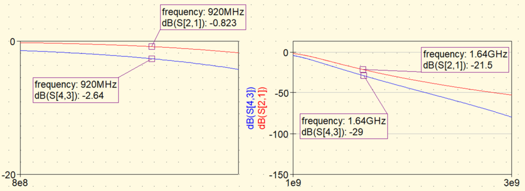
Here are the S21 results of the simulation. Red – ideal components, Blue – real components

At first glance, the real components seem to have a larger attenuation and better characteristics, but a closer look at the passband and the second harmonic band shows that the passband is significantly attenuated in the real components. This is due to the losses caused by the DC component, parasitic capacitance, and parasitic inductance of the actual components.

In the simulation using the GRM03 series and LQP03TG series, a deviation of about 2dB was confirmed compared to the results using ideal components. This is a level of concern for the impact on performance in actual applications.
Component Optimization and Resimulation
Here, let’s switch to lower loss components, the GJM03 series and LPQHQ03 series. These components are designed to reduce DC components and other losses, and good characteristics are expected.
The following components were used:
- GJM0335C1E5R6BB01 (5.6pF)
- GJM0335C1E4R1BB01 (4.1pF)
- GJM0335C1E1R5BB01 (1.5pF)
- LQP03HQ15NH02 (15nH)
- LQP03HQ10NH02 (10nH)
- LQP03HQ3N7B02 (3.7nH)
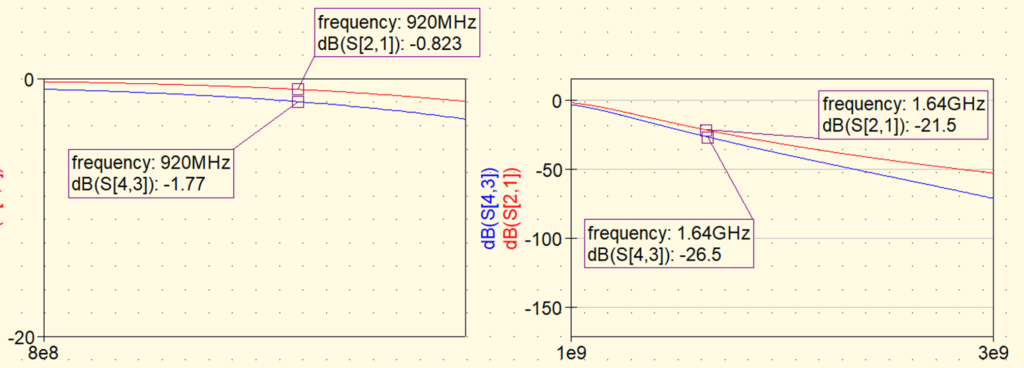
The results of the simulation are shown in the graph below.
You can see that the characteristics are closer to those of the ideal components.

To improve the 2dB deviation, we changed the components to the GJM03 series chip capacitors and LQP03HQ series chip inductors, which are characterized by lower loss, and conducted a resimulation. This change improved the deviation to about 1dB.
Analysis and Consideration
This result demonstrates the importance of appropriately selecting the type of components according to the required performance. The deviation in performance not visible in the simulation using ideal components was clarified by using the S parameters of real components, and performance can be improved by optimal component selection.
Conclusion
Simulation using actual component S parameters with QucsStudio is highly effective in the design process. Especially when fine optimization of performance is required, it is possible to achieve the target performance by testing with different types of components. Through this process, more realistic filter design can be achieved.


Comment