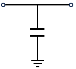
Electronic components have differences between their ideal characteristics and actual characteristics. These differences are due to parasitic elements and resistance components inherent in the actual components. For instance, an ideal capacitor maintains a constant capacitance at any frequency, but real capacitors have parasitic inductance and DC resistance, which alter their characteristics.
This difference is crucial when designing electronic circuits. Non-ideal characteristics can unexpectedly affect the overall circuit operation, necessitating accurate modeling and prediction of these components’ behaviors for precise simulations and reliable designs.
In this article, we will explain how to identify equivalent circuit parameters for chip capacitors using QucsStudio. Mastering this technique can enhance the accuracy of your simulations and improve the reliability of your circuit designs.
Step 1: Acquiring the Actual Component’s S-Parameters
First, we measure the actual component’s characteristics. For this example, we use a 100pF 0.6×0.3mm Multi-Layer Ceramic Capacitor (MLCC).
- S12 Characteristic Measurement: We use a network analyzer to measure the capacitor’s impedance at various frequencies. This measurement helps us understand the actual behavior of the capacitor in detail.
- Data Import: The measured data are exported to a Touchstone format S-parameter file and imported into QucsStudio. This allows us to use the actual measured data in our simulations.

Step 2: Verifying S-Parameters
Using QucsStudio, we display the acquired S-parameters and use them to construct a circuit parallel to the transmission line and connected to the ground (GND).

1. Constructing the Actual Component’s Equivalent Circuit: Open QucsStudio and create a new circuit diagram. First, select the S-parameter component from the ‘system components’ library and construct the circuit as described below.

2. Executing S-Parameter Simulation: Perform the S-parameter simulation for the configured circuit over a range from 100MHz to 3GHz.

As the frequency increases, the impedance of the capacitor decreases, leading to signal attenuation. However, the measured S-parameters show expected attenuation up to about 1GHz, beyond which the attenuation lessens, indicating a difference between the ideal and actual capacitor characteristics.

Thus, the actual component differs from an ideal capacitor due to the presence of inductance and resistance components. Following are the steps to create the equivalent circuit incorporating these elements.

Constructing the Actual Component’s Equivalent Circuit: The capacitor component in QucsStudio includes a feature to describe the resistance component. Using this feature, we add components that represent inductive elements to the equivalent circuit, thus constructing an actual capacitor’s equivalent circuit.

By using this equivalent circuit, we adjust the inductive and resistive components to find values that match the actual component’s characteristics, thus modeling the component.
Step 4: Review and Analysis of Results
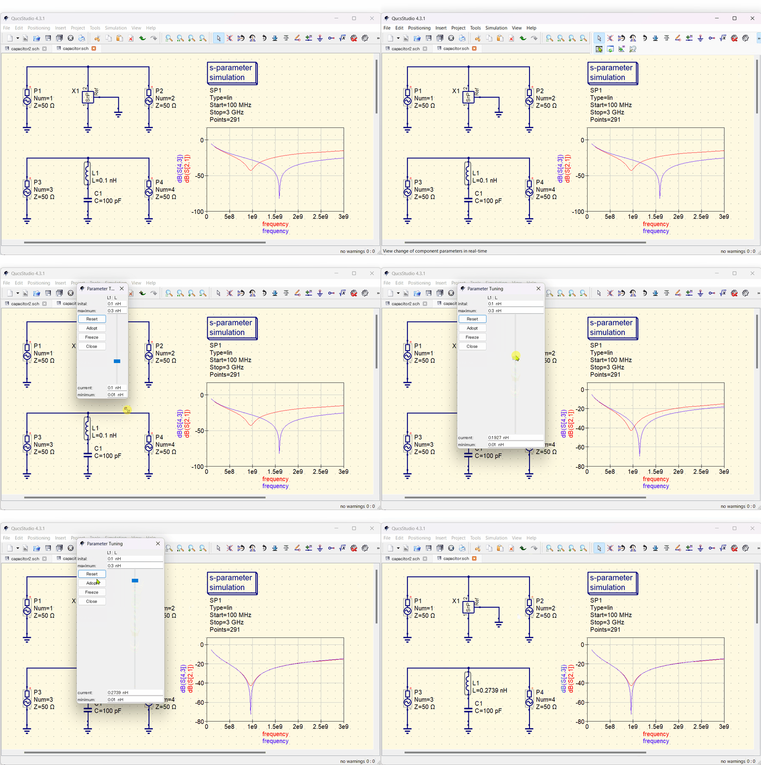
We use QucsStudio’s Tune function to adjust the inductance values and find those that are similar to the actual component’s frequency characteristics.

By referring to the graph, we identify points where the resonance matches, and find that the inductance value at that time is 0.2739pF.
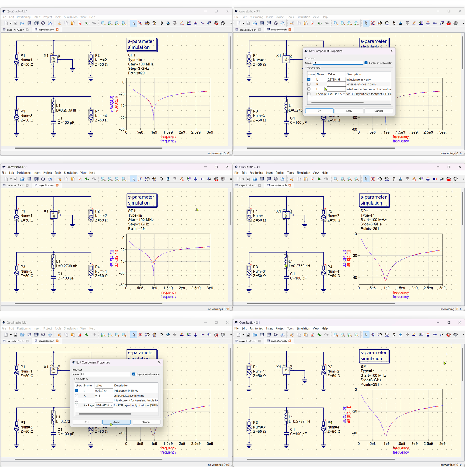
Next, we determine the resistance value. We double-click on the L1 component to open its properties and enter the value for the series resistance.

For a chip capacitor, the resistance is usually set within the range of 0.1 to 0.2 ohms. In this case, setting it at 0.18 ohms provides characteristics nearly identical to the actual component. We achieve the same results using the Tune function to adjust the resistance values, just as we did with the inductance values.
Summary
We were able to extract the equivalent circuit parameters for the chip capacitor using QucsStudio.

This method allows us to precisely understand the behavior of components and achieve more reliable circuit design. Additionally, by using this technique, we can conduct precise simulations based on actual measurement data, improving the quality of our designs.
We hope this guide assists you in enhancing your skills in electronic circuit design and simulation.
📌 See the recommended reading order (Roadmap)
➡️ Next (recommended): Back to Roadmap


Comment