
This time, we will explain in detail the design process of a Low Pass Filter (LPF) for Sub-GHz (915MHz) communication using QucsStudio.
Step 1: Setting the Target Performance
To send radio waves farther, we use an amplifier to amplify the signal. To improve power efficiency during amplification, it is desirable to amplify the signal by making the most of the amplifier’s linear region.
However, pursuing power efficiency can distort the signal, generating harmonic components of n times. These harmonic components can adversely affect other wireless systems, so it is necessary to suppress them below the standards based on the radio regulations of each country. Therefore, it is common to attenuate the harmonic components with an LPF.
This time, we will design an LPF that allows the Sub-GHz band to pass through while attenuating frequencies above it, using inductors and capacitors.
In actual design, it is necessary to individually design the filter according to the characteristics of the device used and the harmonic level aimed for.
As a specific example, we aim to achieve performance equivalent to TDK’s laminated LPF, DEA100915LT-6319A1, and set the performance indicators as follows.
- Insertion Loss: Below 0.5dB (824-915MHz)
- Attenuation: Above 18dB (1648-1830MHz)
Step 2: Initial Design of LPF Using the Filter Synthesis Tool
QucsStudio includes a Filter Synthesis tool that automatically generates filter designs. We will use this tool to perform the initial design of a filter that meets the target performance.
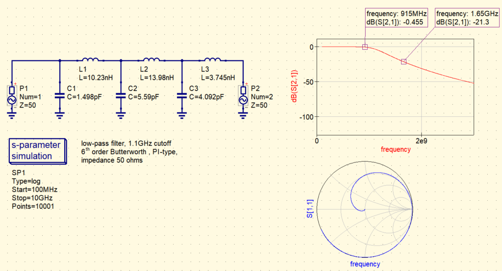
Using Filter Synthesis, we will design a Butterworth type LPF under the following conditions.
Order: 6th
Cut-off Frequency: 1.1GHz
The created filter meets the target characteristics as confirmed.
Step 3: Applying Actual Component Values and Confirming Performance
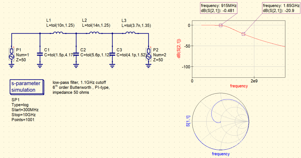
With values close to the constants in the initial design calculation results, select inductors and capacitors available on the market, and change to the following constants to check the filter’s performance.
- L1: 10.23nH ⇒ 10nH
- L2: 13.94nH ⇒ 14nH
- L3: 3.745nH ⇒ 3.7nH
- C1: 1.498pF ⇒ 1.5pF
- C2: 5.59pF ⇒ 5.6pF
- C3: 4.092pF ⇒ 4.1pF
The characteristics still meet the target.
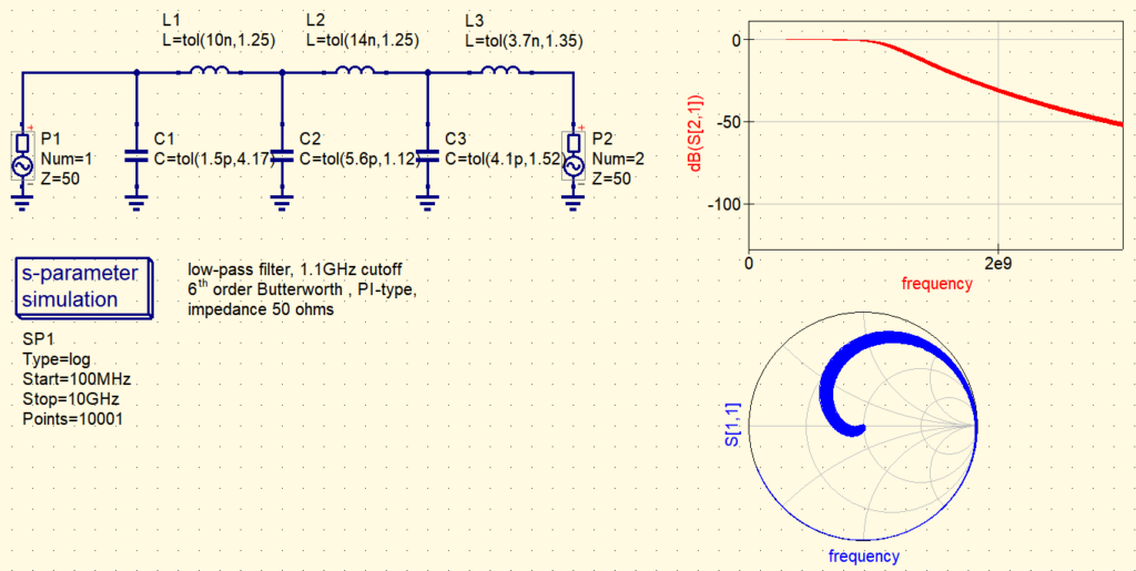
Step 4: Considering Tolerance with Monte Carlo Analysis
Actual components such as capacitors and inductors have variations within the ranges defined by tolerances, and Monte Carlo analysis is conducted to evaluate the impact of these variations on filter performance.

Generally, capacitors, inductors, and other components have lineups with different tolerances. Narrowing the range of tolerances increases the cost of parts. Therefore, it is desirable to use parts with wider tolerances if they do not pose a problem in performance.
First, we will perform Monte Carlo analysis under the widest tolerance conditions to check the characteristics.
- L1: 10nH±5%
- L2: 14nH±5%
- L3: 3.7nH±0.2nH
- C1: 1.5pF±0.25pF
- C2: 5.6pF±0.25pF
- C3: 4.1pF±0.25pF
Assuming a normal distribution for part variations, the largest variation is analyzed as 4σ. For example, for 10nH, 4σ is 5%, so σ = 1.25%.
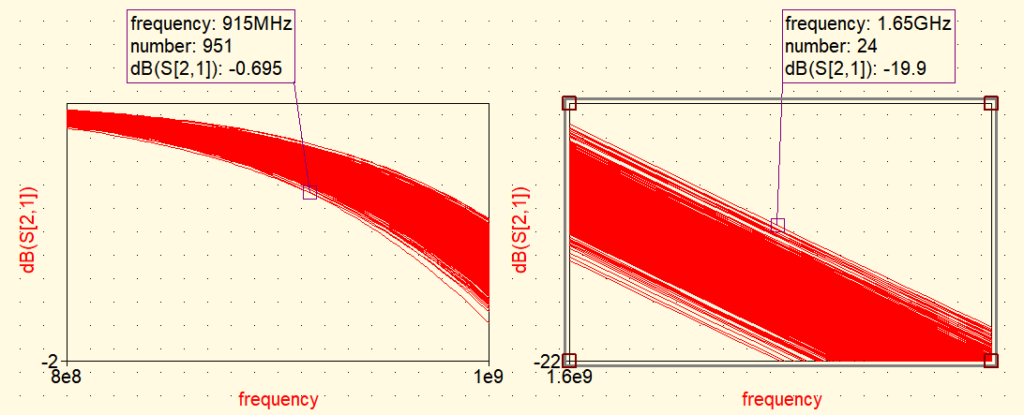
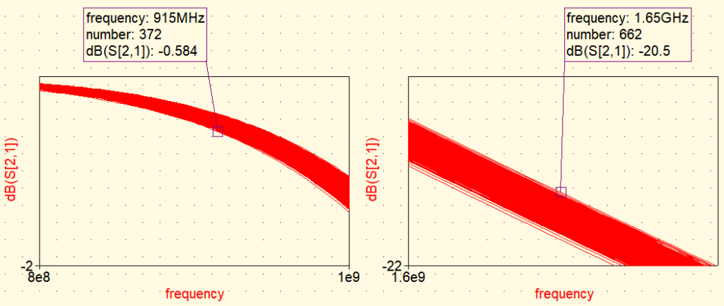
When these variation ranges are considered in the simulation, the worst-case scenario becomes apparent.
915MHz -0.481 ⇒ -0.695dB
1650MHz -20.9 ⇒ -19.9
If the variation is too large, the tolerance of parts can be improved by changing, for example, inductors to ±3%, capacitors to ±0.1pF. Please consider according to the target characteristics in actual design.
Conclusion
Through the detailed LPF design process using QucsStudio, we introduced a method to design a filter that effectively attenuates harmonics in the Sub-GHz band. By leveraging the powerful simulation features and analysis tools of QucsStudio, it is possible to realize a filter design close to the ideal.
The designed LPF and the DEA100915LT-6319A1 aimed for can also be compared using S parameters.
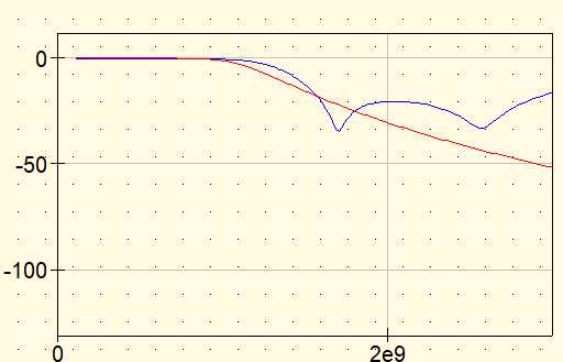
Red: LPF designed in the simulation
Blue: DEA100915LT-6319A1


Comment